|
|
How To Make A Magic Lantern, as described in The Book Of Knowledge. |
|
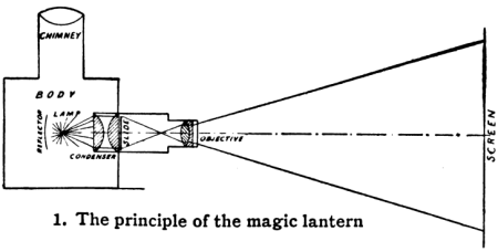
Instructions It is well to mention at once that scientific people do not use the term magic lantern now, but prefer the term optical lantern. The prefix magic arose in an age when scientific men were regarded as magicians, or dealers in the black art, because their researches and methods were not understood by ordinary people. There is no magic or mystery in the lantern, but it is simply an instrument of scientific value, as well as amusement, in which the laws of optics are utilised to enlarge greatly the image of an object on the slide, and to make it appear on a screen. There is much difference between the construction of a high-class instrument of science and the little lantern which we describe here, but the principle is identical in both. The elements of any lantern are, as indicated in picture 1, the body or casing; the condenser, which receives light from the lamp, or other source of illumination, and transmits it through the slide; and finally the objective or magnifying glass, which focuses the light received from the condenser through the slide, and transmits it to the screen. |
|
| A single lantern can be made in several different ways, as well as in different sizes. A very elementary form of magic lantern might be made from an old tin cracker-box, with a cheap wall-back lamp and a simple lens, and a slide carrier made from the wood of a cigar box. But we are going to make something much more like a perfected scientific instrument, even if it entail the expenditure of a dollar or more. We shall adopt the old-fashioned oil-lamp to furnish the necessary light. It is not so bright as oxyhydrogen limelight, acetylene, or electricity, and it is very hot, but good results are obtained with a suitable lamp, well tended, and nearly all the smaller simple lanterns are illuminated in this way. |
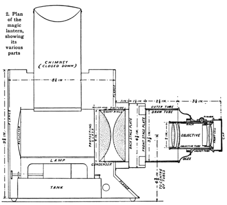
 You will find an enlarged version of this diagram on the next page. |
| In settling the size of the lantern, the cost of fittings must be considered, because what are termed the optical parts' must be purchased, as you cannot make your own condenser and objective, nor can you make very easily the tubes in which they are mounted. | |
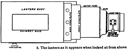
 You will find an enlarged version of this diagram on the next page. |
The most important part of the lantern is the optical. On this depends the
clearness of the picture thrown on the screen. Many of the cheapest lanterns
have simple lenses, but they do not give bright, clear definitions free from
colour rings. To ensure good results, lenses must be combined in certain
fashions, the reasons for which we shall understand some day when we study the
laws which govern the refraction of light. There are many such combinations.
Those which we select for this lantern are shown in picture 2, and are the ones
which are most generally used. The condenser is composed of two plano-convex
lenses, set with their plane faces outermost, forming a compound
condenser. The objective is of the "Petzval" form, so called from its inventor's name. It is achromatic, that is, the image is without colour rings. The diameters are also those commonly used for lanterns of many different styles and dimensions, namely, a condenser of 4 inches diameter, and an objective of 2 inches diameter. These are shown in picture 2, with the method of their fitting in cells and tubes. Even if you have a lathe, their fitting is not an easy task, and therefore you must buy the lenses already fitted in their tubes. Opticians supply these at prices which vary according to quality. Their names and fittings are as follows: |
| A 4-inch condenser, of compound plano-convex type, may be purchased ready in its mount or cell for 2 dollars new, and less if second-hand. The mount is in two parts, one screwed over the other, as seen in picture 2, one ring having a milled head by which to turn the screwed portion off and on. A few air-holes are made, to prevent mist from forming. The back lens is liable to become cracked by the heat of the lamp. For this reason the lenses are fitted loosely in their mounts, so that they will rattle, and the hinder one is often protected with a disc of plain glass, as shown in the picture. | |
|
In essential relation to the condenser is the objective, which receives and
transmits the light passing through the image to the screen. This is shown in
picture 2, and comprises of two distinct sets of lenses in a tube, which is slid
by means of a rack and pinion in an outer jacket or tube -- as also shown in
picture 3 -- which has a connection to the condenser tube. The front combination comprises a double convex lens of crown glass -- the front one in the picture -- and a nearly plano-concave -- actually a double-concave -- lens of flint glass cemented to it with Canadian balsam, the hinder one in the picture. |
 You will find an enlarged version of this diagram on the next page. |
|
This is mounted in a little cell -- the front cell -- distinct from the main
objective tube, and screwed into the latter, to permit of cleaning the inner
faces of both front and back lenses. At the back there is a concavo-convex lens
of flint glass, separated by a small space from a double-convex lens of crown
glass. These are both secured in the rear end of the objective tube as shown.
The front of the objective is often fitted with a hinged cover termed a flasher, which shuts off the image from the screen. In this one a cap is fitted to the front tube, like that used on some cameras. |
|
 You will find an enlarged version of this diagram on the next page. |
An objective of this kind can be purchased ready mounted in a polished brass
objective tube, which slides in another brass tube termed the jacket,
with a rack and pinion for effecting the adjustment. This is essential for exact
focusing. Such mounted objectives are sold at prices ranging from $1 upwards,
according to quality and finish. They can also be bought second-hand. The one we
shall chose should be of 6-inch equivalent focus, which is suitable for
lantern work in ordinary rooms such as we are likely to use. The objective combination is united to a draw tube, through an intermediate ogee, being screwed to the latter. The draw tube is inserted, a sliding fit into an outer tube, as seen also in picture 3, which permits the lenses to be readily taken out of the lantern when not in use. The outer tube is fitted with an internal flange, and soldered to the front stage plate or slide-carrier plate. Between the condenser and the objective the picture slides have to be placed, and sundry plates have to be fitted to effect these connections. Behind the condenser is the lamp. These connections and details will be better studied after the body of the lantern has been made, which work we shall now take up. |
|
In the view given in picture 2, the
lantern is supposed to have been cut down vertically through the centre. In
picture 3 we are looking down on the outside of the lantern from above, In
picture 4 we see the lantern from the side, and in picture 5 from the front, and
in picture 6 from the back. The base is carried forward at the front, as shown
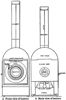
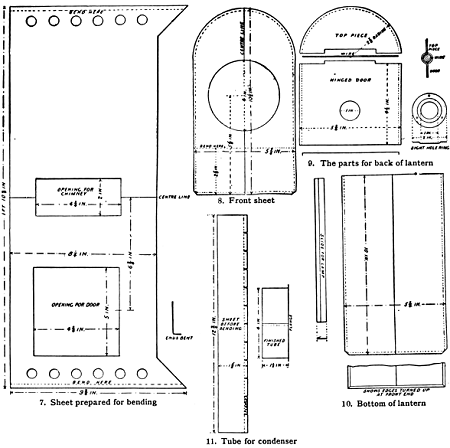
in pictures 2 and 4, to give extra support to the overhanging tubes. The best lantern bodies are made of mahogany, lined with sheet iron, leaving an air space of a quarter of an inch or so between the iron and the wood. We must make something simpler, as shown in the pictures. The body may be built either of sheet iron or of tin. Russian sheet iron is better than the ordinary quality. If tin is used it must be japanned black, but this can be done after it is made into shape. The tin can be cut with a strong pair of scissors, but if you can borrow a pair of shears from a friendly tinsmith the work will be rather easier. It is worked very readily, and you should meet with little difficulty in this part of the task. The lantern body, too, is designed as simply as possible, comprising only four distinct pieces of tin in the main portion. The sides and top are in one sheet, shown in picture 7; the ends are in two pieces, shown in pictures 8 and 9; and the bottom is in one piece, shown in picture 10. |
|
| The sheet for the sides and top is made in one, to avoid jointing the top. It is cut to the dimensions given in picture 7, including an opening for the chimney, an opening for the door at the side, and six half-inch round holes are cut at both ends to afford draught for the lamp. When marking this out, start from the centre line, cutting each half on each side of this line exactly alike, with the exception of the door opening. As you will not cut the edges exactly correct with scissors or shears, a file will have to be used to produce accurate results. Also, the back edge must be finished smoothly, as you might not be able to manage a beaded edge well, which is done in shop lanterns. The sheet must be bent to a semicircle at the centre, as shown in pictures 5 and 6. The easiest way to do this is to plane a block of wood to the curve and bend the sheet round that until it fits the curve exactly. Or you might find a piece of pipe of about the right curve. The extreme ends must be hammered and bent sharply over the edge of a block of iron or wood, as seen in pictures 5 and 6, and enlarged in picture 7, the object of which will be explained presently. The front end sheet, shown in picture 8, is made to the dimensions given, and has one hole cut in it to receive a tin tube, as shown in picture 2, in which the condenser-cell or mount is inserted. This sheet must have its edges, except the bottom edge, bent round from the dotted lines, as shown, to form a little flange to have sufficient breadth of surface to be soldered to the sheet, which has been cut and bent from picture 7. You can just see this flange in picture 2. This can be bent with a pair of pliers, but slits will have to be snipped at intervals of about one inch round the curved portion at the top. The flange can also be bent by hammering it round the edge of a block of wood curved to the radius at the top. Bending at the bottom must be done to correspond with pictures 2 and 7. |
 You will find an enlarged version of this diagram on the next page. |
|
The back end piece, as shown in picture 9, comprises a semicircular piece at the
top and a hinged door, seen also in picture 6. The first is flanged similarly to
the front sheet, picture 8, and soldered to the top of the lantern. But a hinge
has to be made in it, and the door fitted, before the soldering is done. Both
pieces are notched, as shown in the picture, and turned over a piece of wire. An
enlarged detail of this is seen to the right of picture 9. This bending over is
done with pliers, and finished neatly with light blows from a hammer. The edges
of the door are bent backwards towards the lantern body, seen below, to embrace
the sides of the latter. A hole is cut to receive a disc of blue glass, used
only if limelight is employed. The glass is held in by a ring riveted over it to
the door seen to the right. Picture 10 shows the bottom or floor of the lantern. It is turned up and round at the sides and front to embrace the sides and front of the body, as shown in pictures 2 and 6. The bending over is done with pliers, and may be finished by hammering, making a near job without solder. Bent edges are seen at the bottom of picture 10. Knobs are soldered on the bottom to keep the lantern up off its support. The heads of large brass-headed nails will do for these, which are shown in pictures 2, 4, and 6. Two strips are soldered along the bottom inside, within which the foot of the lamp slides along, as seen in picture 6. |
|
 You will find an enlarged version of this diagram on the next page. |
|
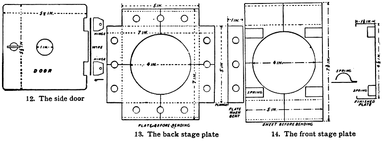
| The door is fitted at one side, with a disc of blue glass in the centre, as seen in picture 4. The hinges are made separately and fitted to the door, and then soldered to the body, as in pictures 12 and 4. The glass dish is fitted as in picture 9. A fastening is made of a bit of brass, filed to the shape shown, and riveted to a pin which passes through the door and has a button on the outside to turn it by. A shop-made door is beaded, but beading may be omitted if the door is made of rather stout material. | |
|
We shall now take up the connection between the lantern body and the optical
tubes. This comprises, as shown in pictures 2 and 3, a back stage plate, a tin
tube, and a front stage plate, shown in detail in pictures 13, 11, and 14
respectively. The back stage plate, as shown in picture 13, is made of a square sheet of tin, notched and cut at the four corners, and bent round square, the cut corner meeting. Three air-holes are also cut in each side, and the sides which are to form the top and bottom are bent round to form flanges, which are soldered to the front as in pictures 2, 4, and 5. A little solder may be run into the corner joints. Before the plate is soldered into place, the tin tube, shown in picture 11, is made by bending a flange on one edge of a strip of tin, snipping it at intervals with a pair of scissors, and bending it to form a circle, soldering the joint. The flange is then soldered to the inner face of the stage plate, and the tube passes within the hole in the front plate of the lantern, as seen in picture 2. The mount rings, or cell, of the condenser lenses fit within the tube, sliding easily therein. |
 You will find an enlarged version of this diagram on the next page. |
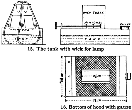
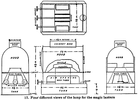
| The front stage plate is made as in picture 14. A piece of plate, cut to the dimensions given, is bent round at two ends, and at each of these ends a narrow flange provided to be soldered to the plate, as seen also in picture 2. Four brass springs are made, and soldered by one end only, at top and bottom within the plate. These are substitute for the more troublesome springs and pins which are fitted to shop lanterns. They yield a little on the insertion of a slide, and so accommodate their pressure to various kinds of slides which have different thicknesses. We come next to the lamp and chimney, seen in position in picture 2, and separately in pictures 15 to 19. Nearly the whole of the lamp is united by solder, and the chimney by means of joints without solder, which would become melted in the intense heat. These lamps are sold very cheaply, complete with a chimney ready to use, but we describe and illustrate one for those who can spend the necessary time over the work. The lamp contains three wicks, each in a separate tube, for burning paraffin which is contained in the tank or reservoir at the bottom, poured in through a brass filler screwed in at one end. | |
 You will find an enlarged version of this diagram on the next page. |
The flanged edges of the tank slide along the ways soldered in the bottom of the body as in picture 6. The wicks are adjusted with the milled heads, each turning a toothed wheel beside its wick. The wicks approach at the top to give one broad flame. Air enters the openings provided at the sides and ends. The smoke is consumed in the hot wire gauze and baffles, within the hood above. The hood is hinged, to throw back, to permit the trimming the wicks. When closed it rests on a light framework of wire soldered to the top of the tank. At one ends of the hood there is a concave polished tin reflected to throw the light onto the condenser. At the other end a sheet of plain glass protects the condenser from excess of heat. Above there is a rectangular frame soldered on, over which the lower end of the chimney fits. The hood must be of blackened sheet, but the oil-tank is of common bright tin-plate. The method of union of the parts is shown in the pictures. |
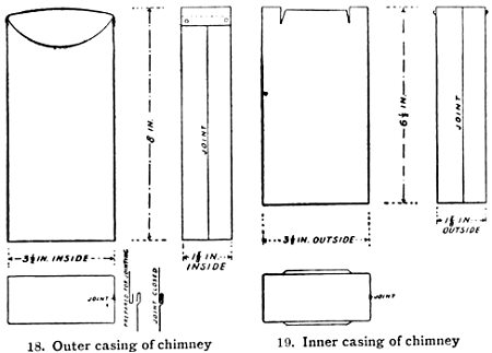
| The chimney, shown in pictures 18 and 19, is made in two pieces, with a telescopic draw. The two parts slide freely over each other. But to ensure that they shall remain as drawn out, at one end a breadth of the iron is snipped and pulled outwards to afford by its springiness a certain amount of friction. |
 You will find an enlarged version of this diagram on the next page. |
 You will find an enlarged version of this diagram on the next page. |
|
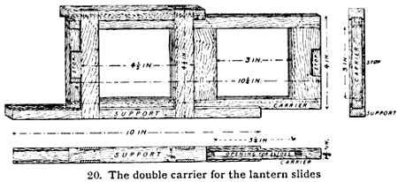
| Picture 20 shows the slide-carrier, which can easily be made of wood from this design. | |
Source:
|
|
| Additions from
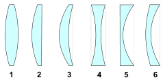
the webmaster: Crown glass is a type of glass often used in lenses and other optical components. It has relatively low refractive index (<1.52) and low dispersion (with Abbe numbers around 60). Flint glass is optical glass that has relatively high refractive index and low Abbe number (50 tot 55 of minder). The currently known flint glasses have refractive indices ranging between 1.45 and 2.00. A concave lens of flint glass is commonly combined with a convex lens of crown glass to produce an achromatic doublet. The dispersions of the glasses partially compensate for each other, producing reduced chromatic aberration compared to a singlet lens with the same focal length. |
|
|
1: biconvex; 2: Plano convex; 3 and 6: concave-convex; 4: biconcave; 5: plano concave. |
 |
| Enlarged diagrams and more.... | |
| |
©1997-2021 'de Luikerwaal' All rights reserved. Last update: 08-07-2021. |
|
